
Because fiber systems are directional, maintaining polarity is crucial. It defines the direction that optical signals travel inside the fiber. Without polarity, data won’t flow the way it needs to.
Ensuring proper polarity means that “transmit” talks to “receive.” In other words, the transmit signal (Tx) at one end of the channel needs to match the corresponding receiver (Rx) at the other end.
Many factors impact fiber polarity—and they all have to do with how fiber components interact with one another:
- General fiber polarity (straight, flipped, crossed, etc.)
- Pinning (pinned/unpinned), often referred to as gender (male/female)
- Orientation
- End-face alignment
- Pinning
- Etc.
The 3 common types of fiber polarity
In ANSI/TIA-568.3, Optical Fiber Cabling and Components Standard, TIA defines Types of fiber polarity components to be used in Methods of polarity, including:
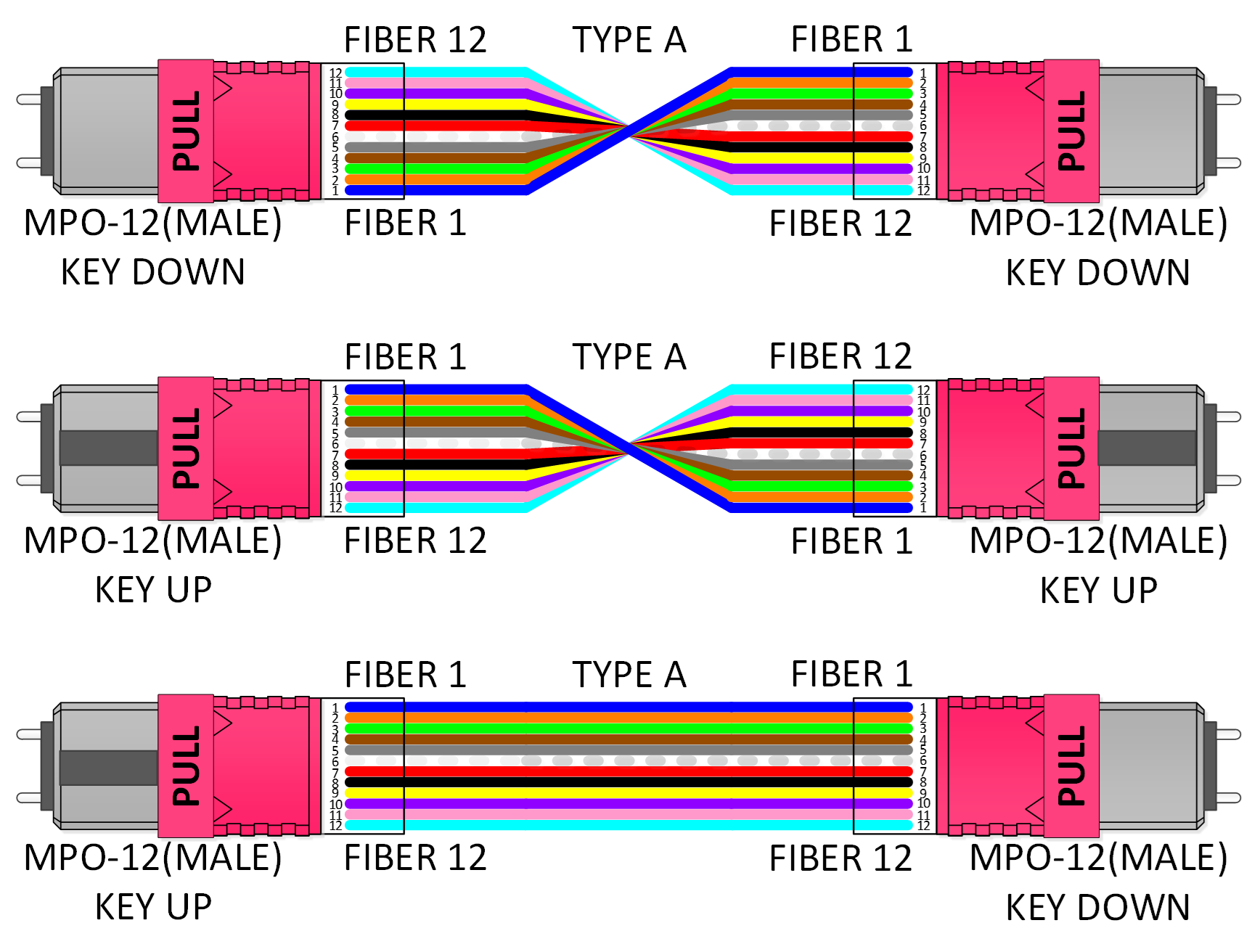
- Type A (straight-through): The fiber at position 1 on one side is the fiber at position 1 on the other side.
- Type B (inverted): A longitudinal “flip,” where the fiber at position 1 on one side is at the final fiber position (position 12) on the other side.
- Type C (twisted-pair): A pair-wise “flip,” where each fiber pair is flipped from one side to the next. For example, the fiber at position 1 on one end arrives at position 2 on the opposing end, while the fiber at position 2 is the fiber at position 1 on the other side.
Stop drawing fiber polarity—and start mapping it instead
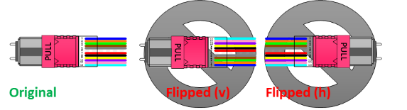
It’s not uncommon for engineers, designers and installers to use graphics software to “draw” fiber polarity for optical fiber cabling systems. Below is an example of what these drawings look like.
Click the images to expand.
These three sketches all represent Type A fiber polarity. Upon first glance, they look different—but they’re actually all the same. The only differentiating factor is the perspective from which the connectors are shown.
While drawing tools may make it simple to draw fiber polarity, they also make it too easy to accidentally manipulate drawings incorrectly leading to an error in polarity planning. For example, a vertical flip changes orientation. A horizontal flip changes fiber position numbering. These mistakes make it difficult to reuse drawings or rely on them to make changes.
That’s why we’re working closely with TIA to change the way the industry draws or maps fiber polarity. While TIA-TSB-5069, Optical Fiber Channel Polarity, aids in mapping and planning, there’s room for improvement.
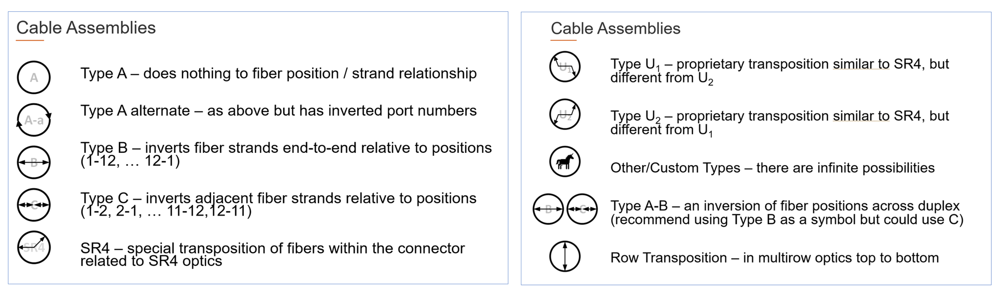
The goal: to shift the industry toward using visual symbols—very specific types of symbols—instead of drawings. Why? Because symbols convey lots of information in a single glance. (Think about no-smoking signs or pedestrian-crossing signs, for example.) They bring order to how the industry describes, visualizes and models fiber polarity.
Within these symbols, we can capture and represent each component’s impact on overall system polarity, including:
- Connector keyway alignment/orientation, such as mating compatibility, pinning and multi-row optics
- Fiber position in the connector
- Strand identifier, such as color
- Port positioning in frames, modules and cassettes
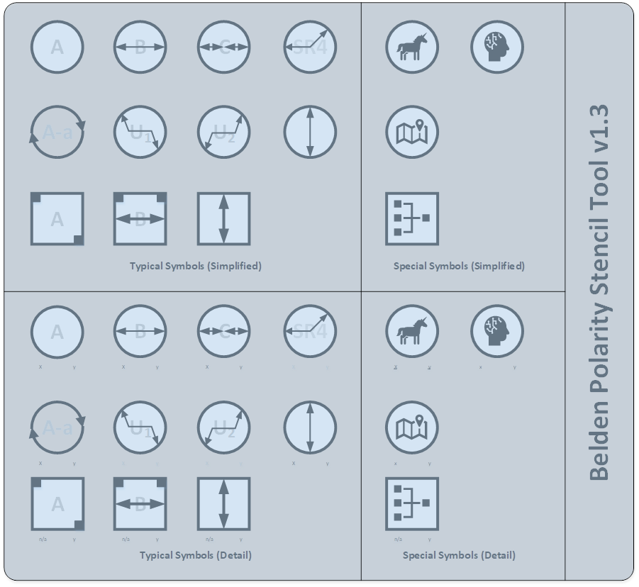
One change we’re suggesting is the shape of symbols. In TIA-TSB-5069, only round symbols are used. The symbols aren’t intuitive or easy to understand, especially when mapping a complex fiber channel. For example, when symbols are all one shape, you can’t keep track of or differentiate between cables and adapters.
For this reason, adapter symbols will be square in shape, while the symbols for cable assemblies will remain round. Inside the shape will be visual information that represents what’s happening inside that cable or adapter.
An empty square or circle indicates nothing unusual with the fibers—everything is as you would expect: one goes to one and so on. Directional arrows or squares displayed inside the shapes visually represent what’s happening with the fiber relative to their position in the fiber connectors.

单击展开图像。
光纤极性映射的优势
使用符号而不是画图进行光纤极性映射具有许多好处:
- 随着它们的扩展(Base-2、Base-8、Base-12、Base-16 等),它们与颜色和颜色代码无关
- 它们不易受到绘图工具可能造成的损坏
- 它们易于使用,可以快速检查配置布局和设计
- 可以将典型字段添加到符号中,以表示绞线股数、引脚、长度、损耗概况等属性。
- 它们允许将特定字段用于零件编号、用途等,从而增加了设计深度。
- 它们构建了一个通用框架,简化了文档记录和培训工作
如果您想了解有关使用符号映射光纤极性的更多信息,以及这对您意味着什么, 请观看我们的 极性映射基础知识 网络研讨会。 我们的两位光纤专家仔细解释了这些即将发生的变化,向您解释了新的符号,并详细描述了这些变化对您和您的光纤项目意味着什么。
单击展开图像。
相关资源:
作者简介
Henry Franc
现场应用工程师
Henry Franc 专注于数据中心的设计、规划和建设,是各垂直领域大型或复杂项目的值得信赖的顾问,负责评估客户的业务需求并找到满足这些需求的最佳技术方案。 他还被业界同仁推选为 TR42 电信布线系统工程委员会副主席。